Getting started with Arduino – Virtual Edition
What is Arduino?
Arduino is an electronics platform that was created to be cheap, accessible, and easy to use for people with little to no programming experience. If you decide to explore the world or making and tinkering, you’ll soon come across mentions of Arduino and see various examples of maker projects utilizing this particular set of devices.
So what exactly is an Arduino? An Arduino is a microcontroller board. Microcontrollers are integrated circuits that are used to control electronic devices. Arduino boards are designed to make the microcontroller included on the board easy to use, by integrating various inputs and outputs that make interfacing with the microcontroller easy via simple connections called pins.
One great thing about Arduino is that the hardware and software is open source. The open source model allows for the designs of hardware and the code of software to be freely distributed. This means that anyone can manufacture their own Arduino compatible boards. Because of this open source model, Arduino has become a popular physical computing platform with a multitude of different types of chips and boards that are used to create a diverse variety of electronics projects.
Tinkercad
Tinkercad is better known as a free, easy to use, web-based 3D modeling program which is very popular within the 3D printing community. But did you know that it also has a virtual programming environment for the Arduino platform? It’s true! If you’ve ever been curious about physical computing and weren’t sure where to start, Tinkercad’s Circuit is a great way to get a feel for Arduino without spending money on an Arduino board and electronic components.
Getting Started - Signing Up For a Tinkercad Account
You will not have to install anything on your computer, but you will need to create a Tinkercad account--if you don’t already have one. To create an account, first navigate to the Tinkercad website at tinkercad.com. Then, after the page loads, click on the white button in the top right-hand corner of the Tinkercad homepage labeled “Join Now.”

You will see a box that will ask if you want to sign up as a student or educator. You will actually want to use the third option, which is labeled “Create a personal account.”
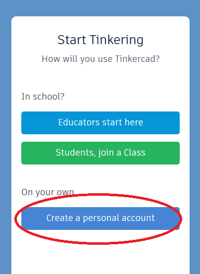
You can sign in using a variety of existing accounts, such as Google, Apple, Microsoft, or Facebook. If you’d rather not have your Tinkercad account linked to any of those other services, you can always just sign up using an email address.
When you enter Tinkercad, you should be greeted with an interface, or user dashboard, that looks like this:
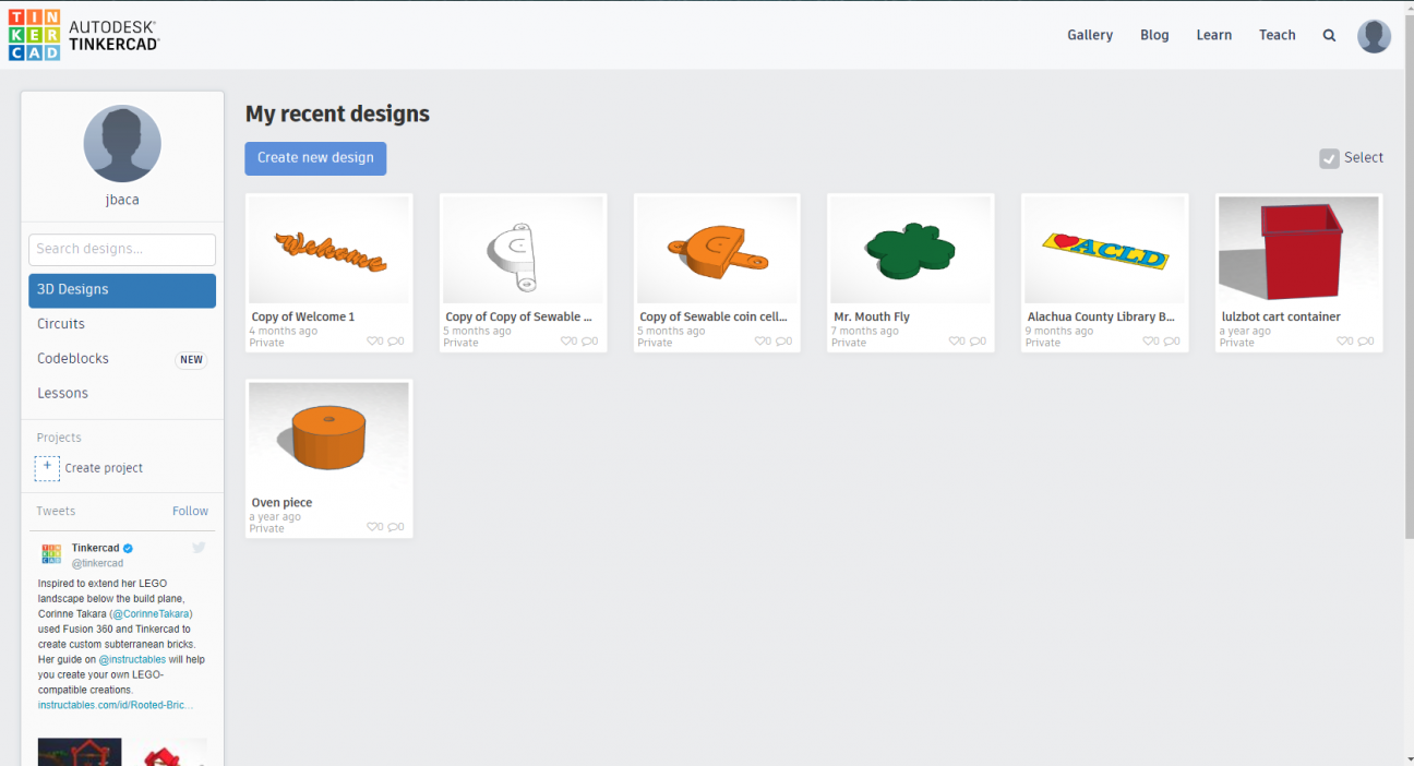
As you can see, I have some 3D modeling projects in my dashboard. What we’re interested in, however--is the Circuits option in the left-hand navigation menu. Clicking on that should take us to a page labeled Circuits that looks like this:
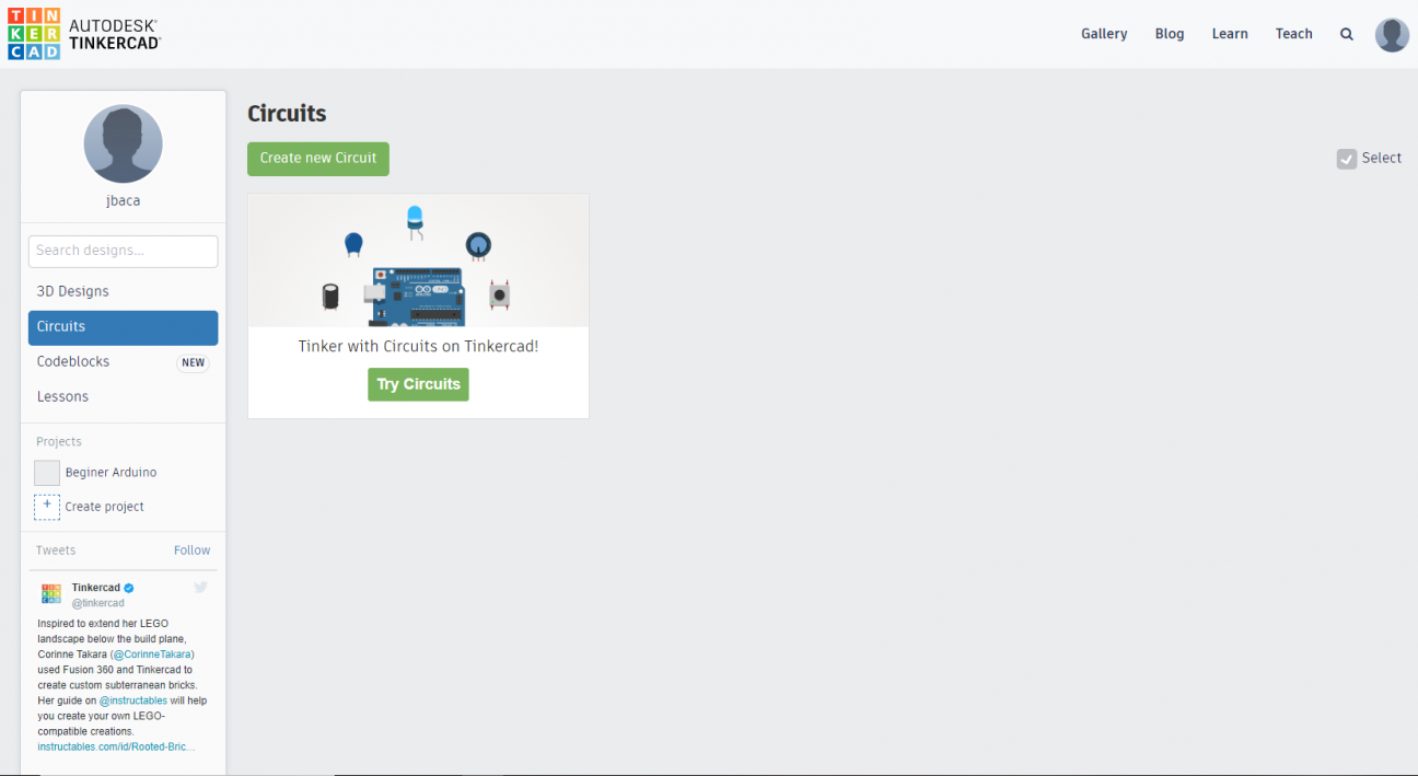
Clicking on the box that says Circuits will walk you through a few short tutorials that will teach you how to use the Circuits interface and that will introduce you to some basic electronics concepts. I recommend taking the tutorial so that you can learn your way around the Circuits interface. The tutorial lessons are fairly brief and completing all three of them should take around 15 minutes.
Once you are done with the tutorial, we can start on our first Arduino project. The one project most everybody starts with is usually referred to as Blink. Both Circuits and the Arduino IDE contain the code for this, and other beginner projects, as part of their package. Instead of just loading the project from the Circuits interface, we are going to start the project from scratch. That way, we can really get a feel for how the interface works and for how the Arduino sketches are coded.
In order to get started, we will have to create a new circuit by clicking on the green rectangular button that is labeled “Create a new circuit.” Clicking on that button will open up a blank workspace for us. You should see something similar to the workspace pictured below:
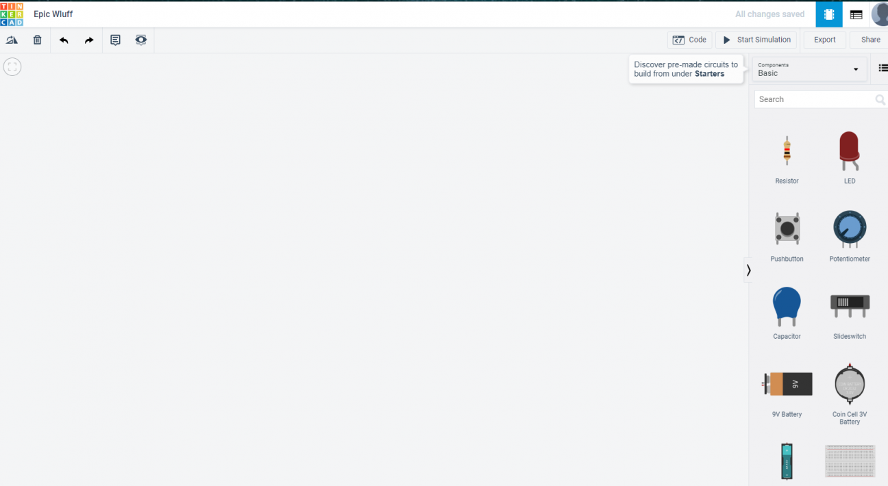
Let’s start by setting up our work area. Since we are working with Arduino, we’ll want to start by adding an Arduino board to our work area. In the right hand side of the screen there is a search bar above a few different electronic components. You can either scroll down, or type “Arduino” in the search bar in order to find the Arduino we will be programming. Once you find the Arduino click on it with the mouse and drag it into the empty work area.
Whenever you click on a component on the work area, you will see a box pop up in the top right corner of the work area. This box works as a label for your components. The top part of the bar will list the name of component, but you can label it whatever you want. The labeling system will default to numbers, but if you are working on a complex project with multiple types of the same component, labeling them by their function might help you keep track of the project components.
Another handy trick is if you click on a component with the mouse, you can then hit the R key on your keyboard to rotate the highlighted component.
Now that we have our Arduino, we need to add a breadboard to the work area. A breadboard is a molded piece of plastic with a series of holes that contain metal lined connection points. This design allows users to quickly add or remove components to a circuit, allowing for the prototype electronics easily and quickly. Below is a diagram of how the holes on a breadboard are connected. You have to keep this in mind when connecting parts of your circuit to each other.
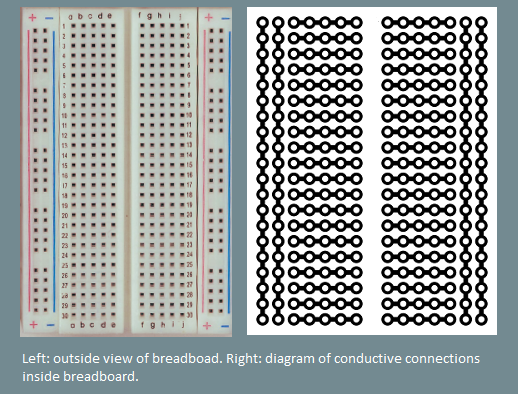
When you search for breadboard you will see a few different types of breadboard. We are looking for Breadboard Small. Add that to your work area and arrange it and the Arduino next to each other. We will be connecting wires from the Arduino to the breadboard for this project.
Blink
The Arduino has an onboard LED light that is connected to the pin connection labeled 13. We could actually just program the Arduino to blink this light on and off, but where is the fun in that? We are going to add our own LED and get that to blink.
The next two items you will have to add to the work area are an LED and resistor. LED stands for light emitting diode. LEDs are durable and don’t require a lot of energy to power, which makes them a popular choice for projects requiring light sources.
Resistors are passive electrical components that restrict the flow of electric current. Remember how we said an LED doesn’t require a lot of power to function? Well, that’s why we need a resistor. The Arduino we are using for this project will supply 5 volts of electricity to our circuit when connected to a proper power source. LEDs typically require around 1.8 to 3.3 volts of electricity to power, depending on the color of the LED. If we don’t add a resistor to our circuit, the amount of current in the circuit could overwhelm the LED and/or damage our Arduino. We need to introduce an electrical component that reduces the amount of electricity flowing to the LED. That’s where the resistor comes in.
The resistor acts like a kind of speed bump for the electrical current in a circuit. Resistors are an important part of controlling the flow of electricity in a circuit. Not all resistors are the same. Resistors are designed to have different levels of resistance. Understanding how much resistance a circuit needs to function properly is where Ohms Law comes in. We’re not going to get into specifics for this lesson, but for our purposes we just need to understand that resistors come in different ratings and that we are going to be using a resistor rated for 220 ohms (220Ω).
Now that we have a resistor and LED in our work area, let’s make sure we have the right value for our resistor. Again, when we click on a component, we will see that component menu pop up. For components with variable properties, we can change the default values. The default value for a resistor in the Circuits workspace is 1000 ohms, or 1kΩ. We can type 220 in the resistance field and then change kΩ to just Ω via the dropdown menu.
You’ll notice that the colored bands on the resistor change when you change the amount of resistance of the resistor. The colored bands are color coded based on the amount of resistance provided by the resistor. That way, you’ll always be able to the value of the resistor if you know how to read the color codes.
You can also change the color of the LED by clicking on it and selecting from the various color options in the dropdown menu.
Building our circuit
First things, first. Before working on any circuit, you should make sure that the circuit is not yet connected to any power source. Never work on electronics while they are powered up! We obviously don’t have to actually worry about any electrical mishaps in a virtual environment, but it is still good practice to work on your circuits just as you would in the real world.
You will notice that while the Ardunio is “unplugged” while the simulated circuit is not active. Once we get our circuit built and ready to run, the Arduino will then be connected to the USB power source.
It’s time to get started. You can do this in any order, but we’ll start by connecting the ground wire to our components. Connecting one end of a wire to the GND pin on the Arduino and the other end to negative end of the LED light helps the electricity flow through the circuit.
When you hover over a connection point of a component in the Circuit interface you will notice that a tooltip pops up showing the name of that connection point and highlighting it in red. To connect that point to any other in your work area, click on that point. You will notice a line emanating from your cursor as you move the mouse to the next connection point. That line represents the wire you would use to connect these points in the real world. You can change the color of the “wires” you connect by clicking on the wire and selecting a new color from the color options in the drop down menu that appears. Similar to the process of changing the color of the LED light.
After clicking on the GND pin, hover over to and click on one of the connection points on the negative rail on the breadboard. (I‘ve chosen row nine, but it doesn’t matter which you choose.) You’ll notice that all the negative holes are highlighted whenever you hover over any one of them. This is because these holes are connected to each other. The same is true for all the other sections of the breadboard. Understanding how these different sections on the breadboard are connected and isolated from each other will help you design your circuit.
Next, pick another point on the negative rail, and connect that point to any point on one of the numbered rows labeled a through d.
Now we are going to add our LED light to the circuit. LED lights have a positive and negative end. The positive end is called anode and the negative end is called cathode. In the real world the positive end is longer than the negative end. In Circuits the positive end of the LED is bent. When you hover over either end of the LED you Circuits will tell you which is which. I’ve rotated my LED so that I can align the negative end of the LED with the negative wire on the breadboard. The negative end is in the same numbered row of the right side of the breadboard. Right now the GND pin and LED are not actually connected. The rows in columns a through e are not connected to the rows in columns f through j. We are going to use the resistor to bridge this gap.
Resistors don’t have negative or positive ends. In addition, for the purposes of our simple circuit, it doesn’t matter where we place the resistor in the circuit either. The only thing that matters is that the resistor is present in order to dissipate some of the excess electricity in order to keep the LED from burning out.
Let’s click on the LED and position it and place it on the board so that it connects the GND wire to the negative end of the LED. So in my example, one end of the resistor is in hole d8 and the other end is connected to f8.
Now let’s connect the positive end of the LED to the board at pin 13. When connecting this wire to our project, it might be a good idea to change the color from the default black, so we can differentiate the different parts of our circuit more easily. I’ve chosen to change the color of the wires in this part of the circuit to red. Pin 13 on the Arduino board is the pin that has the onboard LED connected to it. It doesn’t really matter which pin we use for this, but the code that is usually already set up for this uses pin 13. So your project should look like the following:
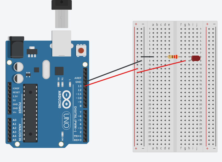
Now that we have our project wired up, we can go ahead and take a look at the code that will get our LED to blink on and off.
Coding your Arduino Project
Now that we have our project wired up, it’s time to work on the code that will control the behavior of our components. The Circuits virtual environment is unique in that it defaults to a visual programming language based off of the most popular of these style of program languages—Scratch. Visual programming languages are simplified versions of coding languages used to teach beginners how to program. The reason that this is unique is that Arduino is usually programmed using the Arduino IDE which you can download for free on the Arduino website. IDE stands for integrated development environment. Integrated development environments are programs designed to help computer programmers code computer programs more easily and efficiently.
Programs written in the Arduino IDE are called sketches. The programming language used for writing sketches is based off of a programming language called Processing, which is a programming language designed to be easy to learn and utilized by visual artists.
So instead of using the Scratch coding interface, let’s just go ahead and dive into the regular Arduino programming language. In the Circuits interface, you upper, right had side of the interface, there is a menu of which the first item is labeled Code. Click on that button and you should see something like the following pop out of the right-hand side of the interface:
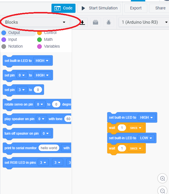
I’ve highlighted the dropdown menu you will need to click on in order to change the view from Scratch to the Arduino programming language. Select Text from the dropdown menu. You will see a message pop up asking if you are sure that you want to stitch programming styles. Click on the continue button. You should now see something like the following screenshot:
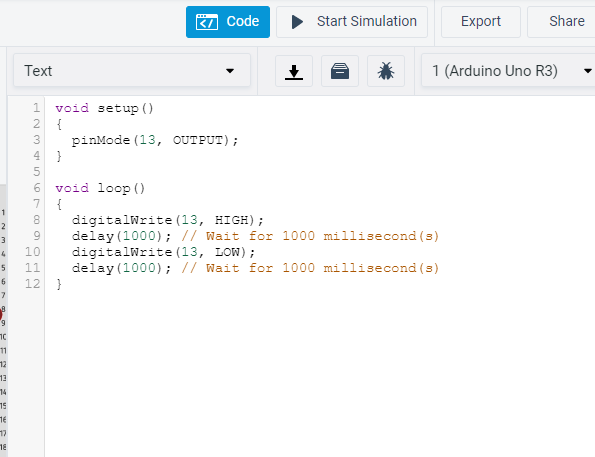
That text is what an Arduino sketch looks like. The Circuits environment automatically loads the code for the Blink tutorial when you start an Arduino project. So we won’t have to code anything from scratch, but we will take a look at the code before we activate our project, so we can better understand how an Arduino project is coded.
Looking at the sketch, you might notice that there are two different sections to the code. One is labeled setup and one is labeled loop. Arduino sketches have to contain these two functions. (They can have more, but must have at least these two.) A function is a grouping of programming language that is used to tell the computer to perform a task.
The setup function for our Blink sketch runs on startup and tells the Arduino that we are going to be using pin 13 to control our LED by outputting an electrical impulse from that pin. The loop function runs repeatedly is what is controlling the output of the pin. The loop function is telling the pin, pin number 13--which is one of the Arduino’s digital pins--to output a high voltage signal for 1000 milliseconds and then a low voltage signal for 1000 milliseconds. Since this function is a loop, these instructions will repeat indefinitely. As you can probably guess, this means that the LED will shine brightly for 1 second, then turn off for 1 second repeatedly causing the LED to blink on and off. (When a pin is set to output, high will set the output of the pin at 3 to 5 volts, depending on the voltage of the Arduino board you are using. Low will set the output to 0 volts.)
In order to see the sketch in action, let’s hide the code by clicking on the Code button again, and then clicking on the button labeled Start Simulation. If your components have been wired correctly, you should see that the LED we’ve connected to the Arduino will start blinking. Congratulations! You’ve just completed your first Arduino project.
Additional Resources
Since Arduino is open source, if you go looking for Arduino compatible microcontrollers, you will find a lot of options available. It might be a good idea to think what kind of projects you are interested in before you purchase a board. For example, is space a consideration? How about power? Some smaller boards have can only handle projects with lower power requirements. Figuring out the parameters of your project will help you determine what type of microcontroller you will need.
The library has a number of resources you can access in order to learn more about Arduino. Our Safari database has a number of books on Arduino programming and projects. Our Lynda database has a number courses on Arduino as well. Happy making!